A Primer on High Frequency Antennas
Users of the High Frequency radio services often desire a single antenna having excellent performance over a wide frequency range. In the interest of efficiency and impedance matching, most antennas used for radio communication are generally resonant antennas. Unfortunately, resonant antennas by their nature operate over a very narrow range of frequencies. To be resonant at a specific frequency, the antenna elements must be made to a certain specific length for that given frequency – as you tune away from the frequency, performance rapidly declines.
Three commonly used resonant antennas are the dipole, vertical antenna and Yagi antenna. A dipole antenna is comprised of a single element, usually one half of a wavelength long at the design frequency. It is then usually split at the center where electromagnetic energy (RF) is then fed. Vertical antennas are basically dipoles oriented in a vertical plane with one half of the element being driven and the other half removed. The earth is then used as a conductor in its place.
Read More
Yagi antennas, frequently referred to as parasitic arrays, are known to provide directional transmission and reception with a high front-to-back ratio as well a low VSWR throughout a very narrow band of contiguous frequencies.
Most embodiments of a Yagi antenna use a single element that is driven from a source of electromagnetic energy.
Arrayed with the driven single element are the reflector and director elements that are not driven directly, known as parasitic elements. There is usually only one reflector and one or more directors, with the favored direction of transmitting and reception towards the director elements.
The Yagi antenna is by design a single frequency device that can be made to perform satisfactorily over a few percent of the center-design frequency. However, tradeoffs must be made between gain, front-to-back ratio, and VSWR to allow the antenna to perform over this very narrow 2%-3% range. It is often desirable to have a single Yagi antenna operate in multiple frequency bands. Many radio services have assigned frequency allotments segregated into bands, scattered through the high frequency radio spectrum, ranging from 3 – 30 Megahertz (MHz). Radio services commonly use Yagi arrays in the 6 MHz and higher frequency range.
Prior to SteppIR Communication Systems arrival on the market in 2001, to enable wider frequency coverage, three methods have been classically employed. A common method is the use of “traps” that allow one element to function on three bands. Traps are parallel-resonant circuits placed at specific locations on the element to decouple a portion of the element automatically as the antenna operation is changed from band to band. Although multi-element trapped antennas cover multiple frequencies with fewer elements than other manufacturers designs, they cannot be optimally tuned and there are significant losses associated with traps in all the elements- including the driven element. A trapped Yagi antenna represents a significant compromise in gain, front-to-back ratio, and overall efficiency.
Another method to obtain wider frequency coverage is the use of a so-called log-periodic antenna, in which every element is RF-driven and no element is parasitically driven. This type of antenna can operate over a range of frequencies having a ratio of 2:1 or higher. The antenna impedance varies logarithmically so the VSWR can range as high as 2:1 or more. The log-periodic antenna offers wide-bandwidth at the significant expense of gain and front-to-back ratio. The log-periodic antenna typically has approximate gain and front-to-back ratio as a two-element monoband Yagi antenna- yet requires many more elements and a complex feed system.
Finally, there is the use of an open-sleeve cell type of driven element. This method uses one or more parasitically excited elements placed very close to the driven element. The length of these parasitic elements is usually half that of the driven element. This method results in a wider VSWR bandwidth. However, the open-sleeve technique only applies to a driven element. Yagi antennas require additional dedicated parasitic elements for each anticipated frequency band, which can cause unwanted interaction between the elements and affects antenna performance.
Why SteppIR Defense
Our tunable antenna system allows setting the resonant frequency of a single-element or multiple element antenna to almost any frequency, limited principally by the frequency-range of the antenna. These tunable antenna systems employ stepper motors that adjust the lengths of the conductors forming the antenna elements, under the control of an electronic device.
Read More
In addition, various software programs have been developed to model antenna performance based on the physical characteristics of the desired antenna. The Numerical Electromagnetics Code (NEC) is a popular modeling system for wire and surface antennas. Multiple versions of this software, e.g., MININEC, Auto-EZ and EZNEC are marketed to the public. Use of these antenna-modeling software products enable the user to determine the characteristics of an antenna prior to physically constructing the antenna and provides information concerning the changes in antenna properties resulting from changes in characteristics such as the length, thickness, spacing, and orientation of the physical conductors that will be assembled to form the antenna.
SteppIR antenna systems, when used with such software-modeling programs, allow a user to visualize the performance of the as-tuned antenna -and then implement into use: forward gain, beam width (defining the angle between which the forward gain decreases from a maximum level at 0° in both directions to a preselected attenuation usually expressed in dB), front-to-back ratio, (expressing the difference between the gain in the forward direction (at 0°) and the rear direction (at 180°), and front-to-side ratio (expressing the difference between the gain in the forward direction (at 0°) and at opposing sides of the antenna (at 90° and at 270°, respectively). Because Yagi antennas are resonant antennas, antenna bandwidth (the range of frequencies at which the standing wave ratio (SWR) is below a threshold level—usually 2:1) may also be an important antenna characteristic. With older technology such as fixed length Yagis or Log Periodic arrays, designers of such systems would be faced with a conundrum of which of these specific attributes to optimize in their design – at the significant expense of performance.
The behavior of our mechanically tunable antennas can also be predicted using antenna-modeling software. Our systems employ electronic controllers that drive stepper motors to set the lengths of the individual antenna elements for that specific frequency. The controllers are shipped to customers with default element lengths programmed into them for different frequency ranges, easily customizable.
Dynamics that can be computer-modeled and implemented into the controller:
- Maximum gain dBi
- Maximum front-to-rear dB
- bi-directional signal
- 180 degree signal change
- Signal rejection patterns
- Antenna beamwidth
- Modeling performance to a specific antenna height
- Antenna take-off angle
- Antenna Wavelength
Full remote-control, anywhere in the world
The new patented OptimizIR 2 controller brings Software Designed Antennas to an entirely new platform.
Now users have full remote capability, allowing the ability to remotely conduct frequency changes, retract antenna, and access mode changes. The controller also allows for full remote control of all “setup” menu options: calibrate antenna, retract elements, auto-track settings, band limit settings, transceiver setup, motors test, relay test, software version, antenna selection, reset user data, fault code menu, LCD display setup, flash file menu and create/modify antenna mode.
Other features:
- Expanded memory – create and save more antenna models
- Robust, commercial grade grounding of controller circuitry
- EASY firmware updates through USB port
- EASY antenna model updates through USB port
- Improved operating functionality
- Prior programming artifacts removed from firmware and antenna model file
- Optimized for 6.8-30 MHz commercial frequencies
- Can be optimized for user specific frequencies bandwidth, forward gain/front-to-rear based on antenna height off ground (contact SteppIR)
How does it work?
Each element consists of a stepper motor that has two sprockets attached to it. The stepper motor drives the conductor, which is an indexed copper strip, in opposite directions, forming the dipole element or the parasitic element. Each element length is determined by the models inside the electronic controller, and each element is the exact length required at every frequency. For multiple element antennas, the length will vary depending on the element type – driven, reflector or director. The conductor is a flat strip, and it resides on the inside of hollow non-conductive tubes that run the length of the element – these tubes are present only for the physical support of the conductor. The electronic controller is connected to the antenna via shielded control cable, with 4 conductors required per element. Wireless connections between the antenna and the controller are also available.
MIL540C-HP
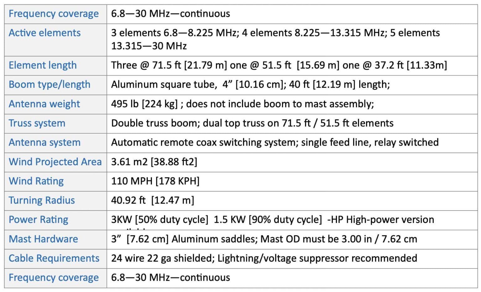
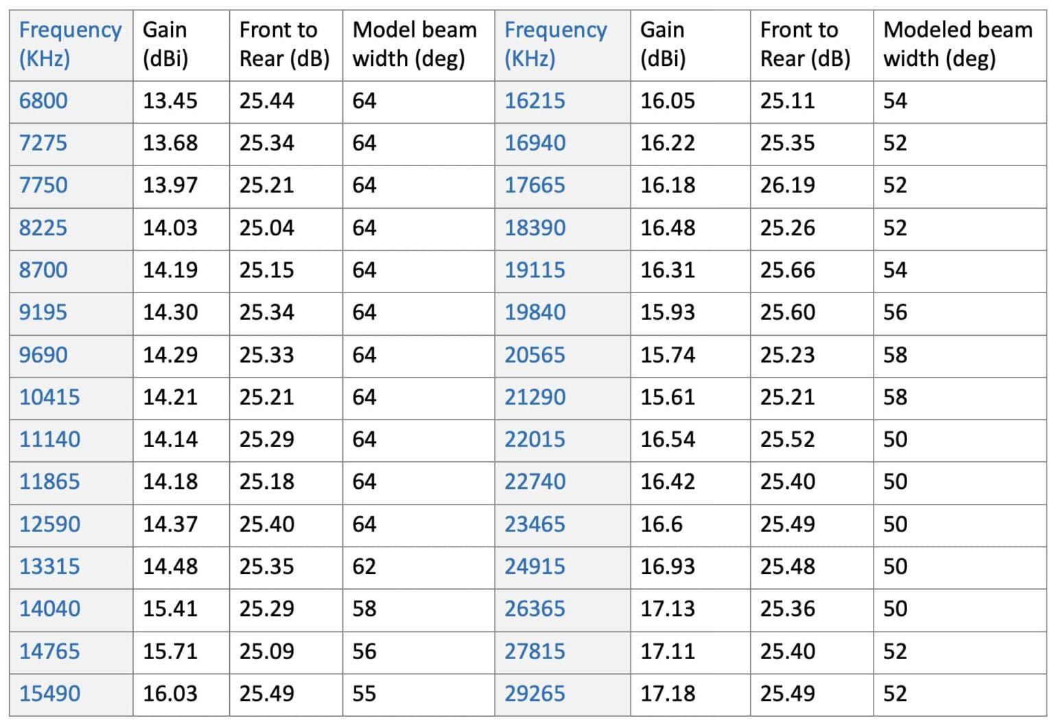
The MIL540C series antenna represents our largest commercial Yagi. Designed for extreme weather applications, high power and significant duty cycles, this product utilizes straight, non-loop elements to ensure simplicity of operation and mechanical longevity. Optimized for performance in the 6.8-30 MHz portions of the commercial high frequency range, the performance offers a minimum of 13 dB gain (modeled at 130 feet) and 25 dB of Front-to-rear signal rejection. With the longest element at 70 feet, 40 foot boom length and five active elements, this antenna offers the best single-antenna performance in the world within it’s physical footprint. This antenna is shipped in a partially preassembled form, reducing onsite labor by up to 40%. The MIL540C-HP Yagi is our high power version of this antenna.
Read More
MIL 540C-HP Specifications
MIL540C-HP Gain / Front-to-rear
at 130 ft height
MIL423C-HP
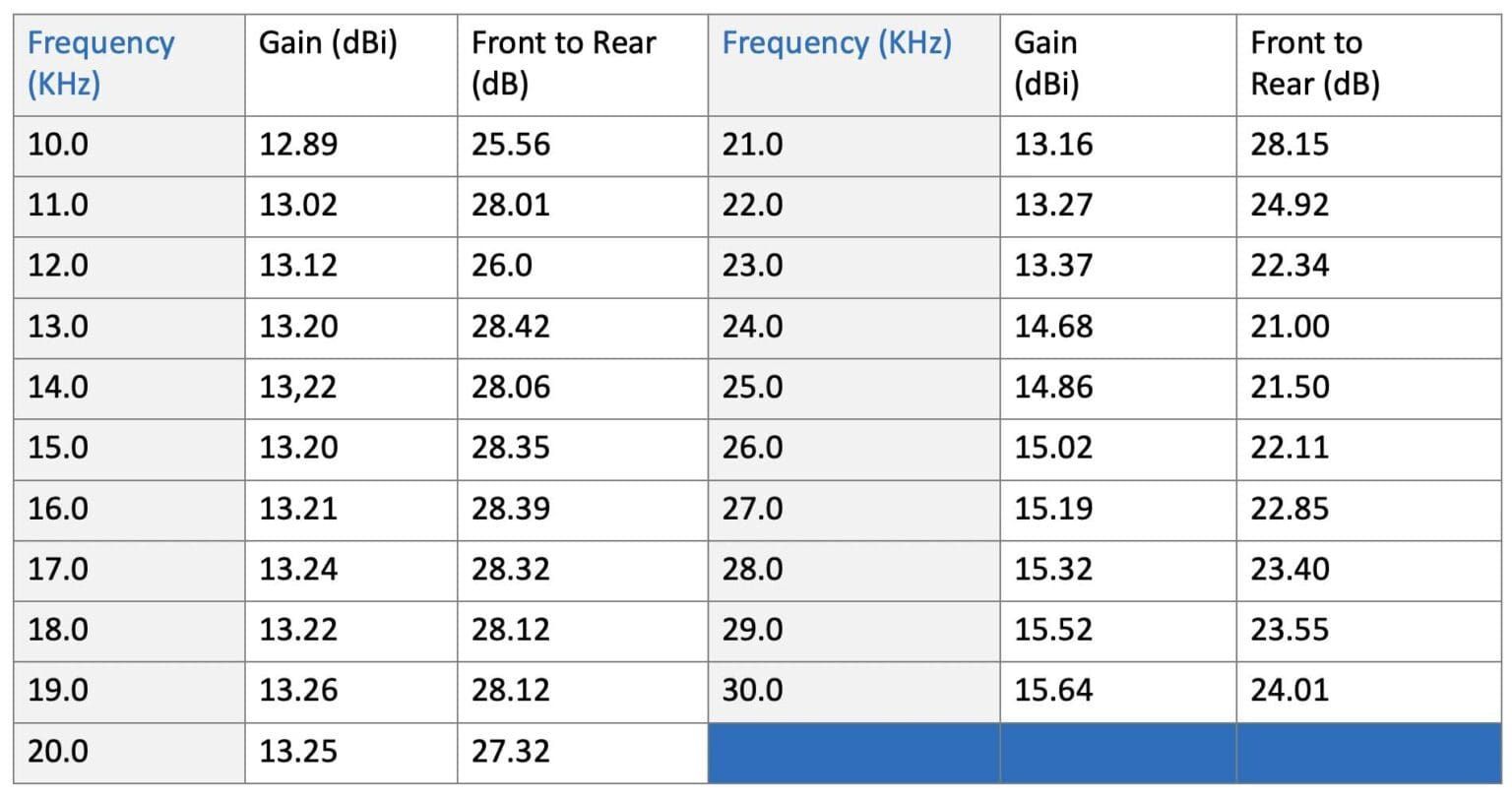
The MIL423C-HP covers 10-30 MHz continuously. It has three active elements when using the 10-13.5 MHz frequency range, and has four active elements on 13.5-30 Mhz. The MIL423C utilizes a tubular, tapered boom and employs a double boom truss. The boom length is 23 feet. This Yagi is meant for use in the higher HF frequencies, and while a smaller physical footprint that the MIL540C, this antenna offers fantastic gain and front-to-rear performance within it’s continuous frequency range of 10 MHz – 30 MHz. The MIL423C-HP is available in a high-power version.
Read More
MIL423C-HP Specifications
MIL423C-HP Gain/Front-to-rear
at 130ft height
MIL319C-HP
The MIL540C series antenna represents our largest commercial Yagi. Designed for extreme weather applications, high power and significant duty cycles, this product utilizes straight, non-loop elements to ensure simplicity of operation and mechanical longevity. Optimized for performance in the 6.8-30 MHz portions of the commercial high frequency range, the performance offers a minimum of 13 dB gain (modeled at 130 feet) and 25 dB of Front-to-rear signal rejection. With the longest element at 70 feet, 40 foot boom length and five active elements, this antenna offers the best single-antenna performance in the world within it’s physical footprint. This antenna is shipped in a partially preassembled form, reducing onsite labor by up to 40%. The MIL540C-HP Yagi is our high power version of this antenna.
Read More
MIL 540C-HP Specifications
HFT540C-HP Gain / Front-to-rear
at 130 ft height
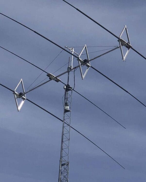
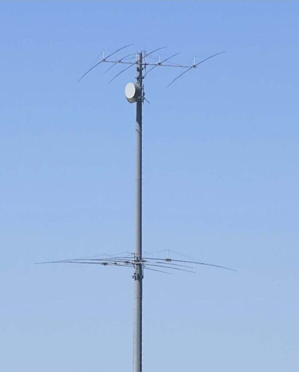
Why Stack Yagi Antennas?
Typically in government HF antenna installations you will see a single massive log-periodic antenna mounted on a tower mounted anywhere from 60 to 150 feet high. This approach gives modest performance over a reasonably wide frequency range, but no thought has been given to the optimal wave angle such a system produces. The only reason Yagis are mounted high above the earth is to take advantage of the inescapable reflection of the RF wave that emanates from the ground. This wave recombines with the direct skywave either destructively or additively at some angle.
Read More
The additional signal strength is approximately 5.5 dB which is a very significant increase, especially considering it also improves received signals by the same amount. The problem is twofold, optimal wave angle is very dependent on the distance of the desired communication path, and destructive groundwave/skywave combinations create deep nulls at some wave angles. The height of the F-layer in the ionosphere also varies throughout the year so this all plays together to make the reality that there is no perfect antenna height. A simple solution to this problem is to avoid the single log-periodic example above and instead, vertically stack two or more identical Yagis. The advantages are substantial:
- Each Yagi provides additional gain on the order of 2.5 dB per antenna with slightly diminishing returns as the number exceeds 4 antennas. A stack of antennas will perform as well or better than one very expensive and very heavy single antenna.
- The deep nulls are virtually eliminated, and the forward power lobe is much more uniform.
- Different antennas can be selected to work together to improve signal strength (in both receive and transmit) at different wave angles. Future antenna systems we would propose to you would have dynamic forced phase (time delay) to each antenna (electronically) that would automatically change the phase to each antenna to affect the best wave angle possible.
- The stack can be used on two different frequencies by switching individual antennas to a different transmitter.
- If individual rotators are used on each antenna broader azimuth directions can be covered, i.e. two receive stations in different directions can hear the transmission
- Since there are multiple antennas in a stack, reliability is greatly increased because the probability of two or more antennas failing at once is low.
The reality of skywave HF communication is that once the ionosphere’s ability to reflect the radio drops to near the noise level the amount of additional power and antenna gain required becomes impractical from a cost perspective. It is more important to have the ability to select another frequency that is supporting ionosphere “skip” communications. We propose having a very high-performance system that is RELIABLE and easy to fix and maintain. Throwing 10 to 15 elements on a single antenna, at a single height is simply not effective as compared to stacking smaller, more agile antennas. Of course, as time goes on, and industry success increases with use of our antenna systems, it may make sense to work with us to go “all out” with some very exotic systems. After all, our favorite pastime at SteppIR is helping our customers win the latency wars!
Interested in working with SteppIR Defense?
Contact u